Views: 0 Author: Site Editor Publish Time: 2026-03-09 Origin: Site


LiFePO4 packs tolerate abuse that would destroy a lithium-ion pack, but they are unforgiving about one thing: charge voltage. A cell that should stop at 3.65V will sit at 4.2V for months while capacity fades and the anode degrades, and nothing in the pack complains until it is too late. Specifying a LiFePO4 battery charger comes down to string voltage, charge rate, duty cycle and environment — in that order.
An off-the-shelf lithium charger is built around 4.2V per cell. LiFePO4 operates at a 3.2V nominal figure and terminates at 3.65V, so the two are not interchangeable. Running a LiFePO4 pack from a 4.2V/cell charger means overvoltage stress; running it from an undersized one means lost runtime against the published specification.
The LiFePO4 discharge curve is famously flat, and so is the constant-voltage portion of its charge curve. Because voltage moves so little as state of charge changes, reference accuracy carries more weight than with a 4.2V chemistry: a ±1% window on a 58.4V termination is ±0.58V, and a loose reference becomes a chronic undercharge.
Charging runs in two phases. Constant current delivers 80–90% of the energy while voltage climbs toward the termination point; constant voltage then holds that level while current tapers into the final top-off, which is what lets a pack reach full capacity without pushing any single cell past its limit.
LiFePO4 cells accept charge poorly below 0°C and age faster when charged hot. Temperature-compensated output — lower charge voltage as ambient rises, current held back below freezing — is worth specifying for anything that charges outdoors or in an unheated warehouse.
Two numbers define the requirement: the voltage at which the string terminates, and the current the cells will accept without excessive heating. Everything else follows from the application.
Multiply cell count by 3.65V for the charge voltage. Adjustable chargers with a segmented 8V–87V output cover the practical range for small vehicles, robots and storage packs; strings that terminate above 87V move to a custom output stage.
String | Nominal voltage | Charge voltage | Typical charger class |
|---|---|---|---|
4S | 12.8V | 14.6V | 60–90W |
8S | 25.6V | 29.2V | 120–200W |
13S | 41.6V | 47.5V | 250–400W |
16S | 51.2V | 58.4V | 400–600W |
20S | 64V | 73V | 600–1,000W |
Current comes from capacity multiplied by the charge rate you are prepared to accept. For a 48V, 20Ah pack (about 960Wh), 0.2C gives 4A and a five to six hour cycle — gentle on the cells and ideal for overnight charging. A 0.5C rate gives 10A and a two to three hour cycle, which is the usual compromise between turnaround time and pack life. A 1C rate gives 20A and roughly an hour to 90%, at the cost of faster capacity fade over the pack's service life.
Convert that current into a rating by multiplying by voltage: 10A at 58.4V is about 585W. Add 10–20% headroom for cable drop and high ambient temperatures rather than treating the calculated figure as the ceiling.
Packs above roughly 100Ah often make better use of two or four outputs than of one large single-channel charger: separate channels spread the thermal load, and a single channel failure does not take the whole station out of service.
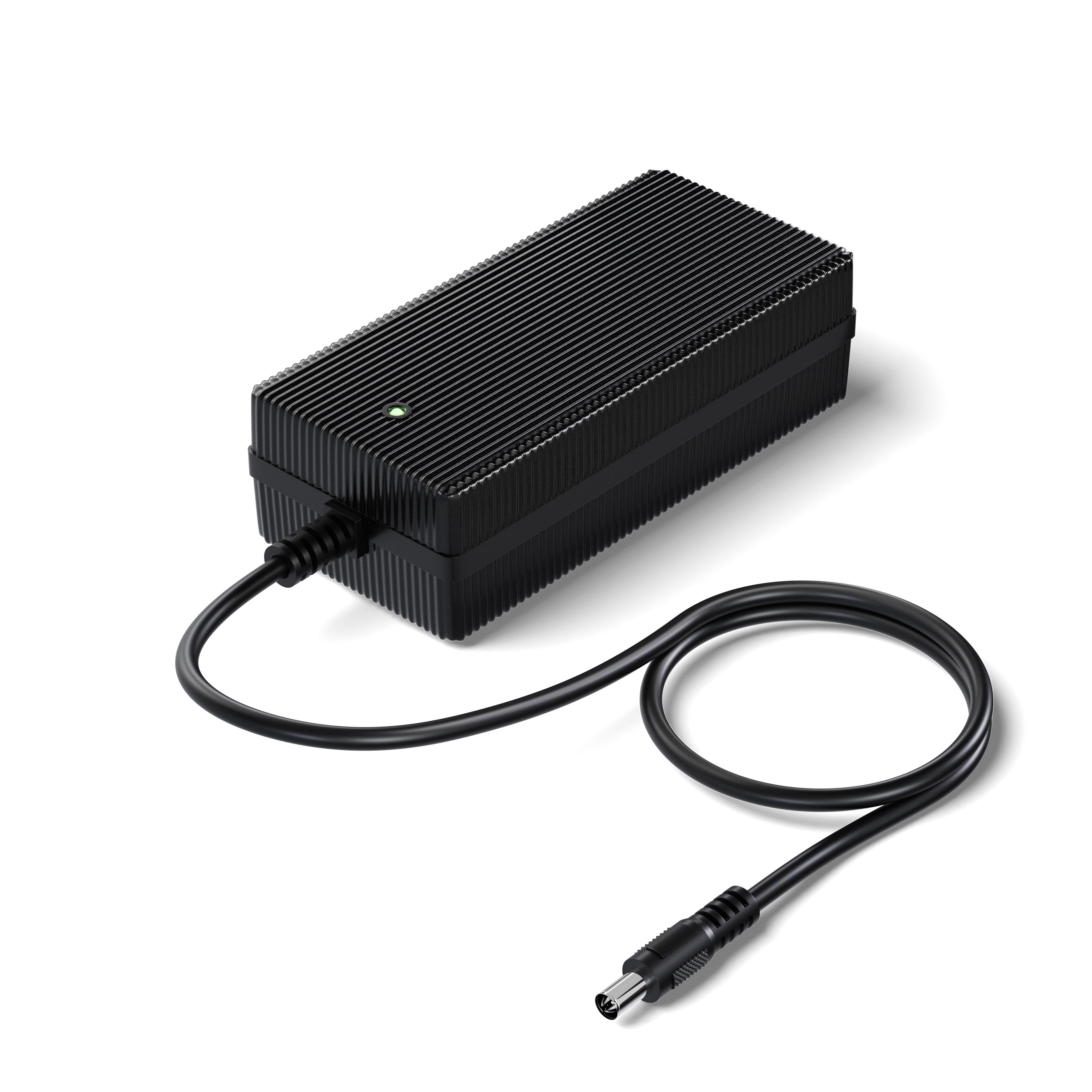
The power class narrows the field quickly; the enclosure decision follows the environment rather than the budget.
60–90W: plug-in and desktop units with 8V–87V adjustable output, used for small packs on tools, portable lighting and compact scooters. IP67 versions exist for outdoor duty.
120–250W: slim and desktop formats, DC-DC variants with 12–30VDC input, dual-output models for redundancy, and 250W IP67 units in aluminium housings.
300W–3kW: rack and bench chargers for motive power packs, four-output 1,000W units, and IP67 models with outputs up to 35A.
Plastic housings keep weight down and suit indoor racks. Aluminium adds mass but moves heat far better, which is what lets a sealed fanless unit hold full output on a summer afternoon. Waterproof models go further: fixed cable entries remove the connector that would otherwise admit water, and potted circuitry keeps moisture and conductive dust off the board.
IP67 is the figure to look for when charging happens outdoors, on wash-down floors or anywhere a hose might be pointed: dust-tight, and tolerant of 30 minutes at one metre of water depth.
Charging from a 12–30VDC source is a different problem from mains: a DC-DC converter conditions the vehicle bus directly, skipping the rectifier and PFC stages, which cuts conversion loss and the heat that must escape a sealed enclosure. Reverse-polarity protection and transient suppression are not optional.
Tip: Match the charger to the highest voltage the string reaches, not the lowest, and confirm the current rating at that voltage: a unit quoted at 20A at 24V will not deliver 20A at 58V under the same power ceiling.
Charge rate, termination voltage and temperature all trade against pack life. Moving from 0.5C to 1C cuts cycle count noticeably. Charging to 3.55V per cell instead of 3.65V sacrifices a few percent of capacity for longer life. Charging in a 45°C workshop ages cells faster than charging at 25°C, which is why temperature-aware output control pays for itself on vehicles that charge in the sun.
Output quality matters as much as the curve. Residual ripple heats the pack internally and can make a BMS misread cell voltages. Keeping it below roughly 100mV, and well under 1% of output, protects both the cells and the electronics guarding them.
For fleets, remote monitoring turns charging from a black box into a managed process. CAN 2.0 and RS485 interfaces let a charger report current, voltage and temperature in real time and accept current-limiting commands from a BMS or station controller — the difference between finding a failing pack in the workshop and finding it after a robot stops mid-shift.
Tip: If a BMS will command the charger, confirm the protocol and register map before ordering. The wrong protocol is a cable you cannot use.
Efficiency translates directly into heat that has to leave the box. A 400W charger at 95% efficiency dissipates about 20W; a 1,000W unit at the same efficiency dissipates around 50W. Inside a sealed enclosure in a warm room, that is enough to push an electrolytic capacitor past its comfort zone, and capacitor life roughly halves for every 10°C of extra internal temperature.
Fanless designs solve this with surface area rather than moving parts: vertical vent paths that let hot air rise and escape, aluminium housings that conduct heat from the switching devices outward, and finned profiles that increase radiating area well beyond the footprint. Past a certain power level the housing material stops being a preference and becomes a design requirement.
Protection layers should be independent so a single failure does not disable all of them. Output short circuit, overcurrent, overvoltage, over-temperature and reverse polarity form the baseline, with fusing on both sides underneath the control loop. Temperature handling works as a staged response: derate when internal temperature climbs, shut down if it keeps rising, restart once the unit cools.
Tip: Leave 10cm of clearance around a fanless charger and never stack units. Derating from blocked airflow looks exactly like a charger that was undersized from the start.
Certification follows the destination market, not the customer's preference. North America needs UL, cUL or ETL plus FCC; Europe needs CE with EMC and LVD coverage, often with TUV-GS; the UK needs UKCA; Japan needs PSE; Korea needs KC or KCC; Australia and New Zealand need SAA or RCM; China needs CCC; India needs BIS; Mexico needs NOM. RoHS and REACH declarations cover material restrictions, and any charger sharing a circuit with a medical device should meet IEC 60601 expectations.
Energy standards are the second filter. DoE Level VI, ErP Stage 2, CoC Tier 2 and Canada's NRCan requirements all cap no-load draw and set active-mode efficiency limits; meeting them is a condition of entry, not a marketing extra. A charger idling at half a watt instead of three watts is a small difference per unit and a meaningful one across a hundred stations running around the clock.
Total cost of ownership usually settles the argument about price. Purchase cost is paid once; energy, downtime and replacement are paid continuously. A charger with an MTBF of 30,000 hours or higher, a three-year warranty, 100% factory inspection and a 4–8 hour burn-in on every unit costs more up front and less across a five-year service window, because it neither wastes energy nor stops a shift. Above a few dozen units, a lifetime cost model is worth more than a quotation comparison.
Fuyuan Electronic develops chargers, adapters and LED drivers across 60W–10KW from bases in Dongguan and Yongzhou: more than 3,000 models, GaN and SiC designs at 120W, 240W and 330W reaching up to 95% efficiency, IP67 options, and OEM/ODM work completing in as little as ten days from a 100-unit minimum order.
A LiFePO4 charging system is defined by four decisions: the string voltage the charger must reach, the current the pack will accept, the environment the enclosure must survive, and the certification the destination market demands. Get those right and the rest is configuration. For reliable products and expert support, Fuyuan Electronic offers high-quality LiFePO4 battery chargers engineered for continuous duty.
A: No. A conventional lithium charger terminates at 4.2V per cell, while LiFePO4 cells must stop at 3.65V. Using one on the other either overcharges the pack or leaves it permanently undercharged, and a slow overvoltage condition may go unnoticed.
A: A 16S LiFePO4 pack charges at 58.4V. At 0.5C that is 10A, roughly 585W, so a 600W charger fits; at 1C it is 20A and about 1.2kW, favouring a 1kW-class unit. Add 10–20% headroom for heat and cable drop.
A: It shortens cycle life substantially and generates more internal heat, so it only makes sense when the cell datasheet and BMS permit it. For daily duty, 0.5C keeps turnaround reasonable without accelerating fade.
A: If the charger is exposed to rain, wash-down or heavy dust, yes: IP67 means dust-tight and able to withstand 30 minutes at one metre of water depth. Fixed cable entries and potted circuitry are what make the rating hold up over years.


